PURPOSE FOR ADDING COOLING FANS
If you have ever taken a telescope out for an evening of viewing and looked through your telescope just as soon as it was set up for the evening, you most likely have noticed it to be a bit blurry or the object being viewed seemed to be rippling. This is due to heat flumes coming off your primary mirror and metal cell assembly as it is cooling down to the ambient temperature. Depending on which type of telescope you use, this could take from 15 minutes to a couple hours, depending on how hot the temperature was where your telescope was stored prior to set-up. The typical cool down time for the 16" Starfinder is about 30 to 45 minutes. The cool down time can be dramatically reduced with the installation of cooling fans.
 |
 |
|---|
PREPARING AND CUTTING FAN HOLES
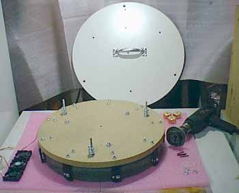
In the photo, (Top Left), you will note that I have removed the primary mirror cell from the Starfinder tube and placed the cell, mirror face down on flexable, soft foam pads. In my case, I used "static resistant" foam used in shipping electronic equipment and less apt to create static that will attract dust to the mirror face.
After you remove the mirror cell assembly from the tube, remove the top “white coated” plate by removing the collimating wing nuts and washers that holds the exterior “white coated” plate onto the mirror cell assembly.
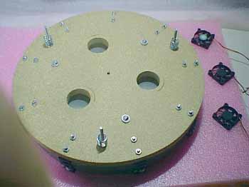
In the photo, (Top Right), drill three holes using a hole cutter drill attachment the size of the inside diameter of the CPU fan to be used. The hole can be a little smaller, but not larger the fan diameter. A hole cutter can be obtained at almost any hardware store and is normally used for cutting large holes in doors for door knob assemblies. The type I used is a universal door-set hole cutter that comes with five removable circular cutting blades. The blade I used was “exactly” the size needed for this purpose. The rear exterior “flange” of the universal hole cutter will prevent you from cutting all the way through the cell particle board plate, stopping just 1/32" short of cutting all the way through the plate. NOTE: This would be a good time to get out your vacuum and clean up the dust created from cutting the holes. Now, just gently tap the center of the plug and it will gently drop to the rear of the mirror below. Using a long shank screwdriver to get under the wooden plug you just knocked loose, raise it up so you can get hold of it and pull it out. Using your finger, rub the bottom of the hole you just cut to remove any loose debris and vacuum inside the holes. You are now ready to install the three (3) CPU cooling fans.
CAUTION:
1. Do not use a hole cutter larger then the diameter of the fan blades.
2. The pilot drill bit in the center of the hole cutter should be adjusted to extend no more then 1/4" beyond the circular cutting blade. If the pilot bit extends too far, the bit will hit the rear of your mirror when drilling the hole.
INSTALLATION OF COOLING FANS
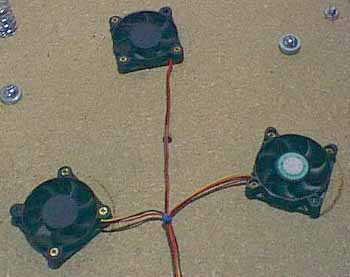
As standard 12 volt cooling fans are too large to install inside the mirror cell assembly area, I chose 50mm case fans, which are the same size as a CPU cooling fan for this purpose due to their low profile. The standard CPU cooling fan is only ˝ inch thick and will fit nicely inside the mirror cell assembly. As they are small, I decided to use three (3) 50mm case fans to generate the air flow I wanted around the primary mirror and metal cell components. I ordered the three 50mm ball bearing case fans from NexFan.com for about $3.99 each plus shipping.
As the screws used,12 each #4 x 1" wood screws, will be inserted into particle board and “very near” the edge of the hole you just cut, drill pilot holes for the screws, using a 1/16" drill bit. This will help prevent the collapse of the holes sidewall when screwing the screws into the particle board.
REINSTALL REAR MOUNTING PLATE
Before installing the rear “white” mounting plate, select a location on the plate and drill a ˝ inch hole in the plate to feed the wires through for mounting a 12 volt female receptacle. ( The hole size will depend on the 12 volt receptacle you decide to use, see below. ) It is now time to reinstall the rear “white” mounting plate. Be sure to feed the fan wires through the new access hole you just drilled in the plate. Secure the rear mounting plate to the cell assembly using the collimating washers and wing nuts you removed in order to remove the rear plate.
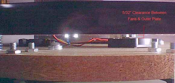
Once the rear mounting plate has been reinstalled, you will note there is about a 5/32 inch clearance between the fans and the rear plate, (see photo above). This is more then adequate clearance for the fans to work properly and allow collimating adjustments.
INSTALLATION OF THE 12 VOLT RECEPTACLE
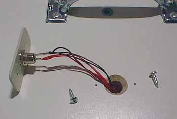
In the photo, above, you will note I am using a Radio Shack Coaxial DC Power Jack, catalogue #274-1563A. The “black and red” wires from the CPU fans are the only wires you will use. The yellow wire you will find on the fans are for a sensor used in computers and not needed for this application. The mounting plate used to attach the Coaxial DC Power Jack to was made from scrap, semi rigid plastic, cut to fit and drilled with three holes. The jack hole is 7/16 inch and the screw holes will very depending on the mounting screws you decide to use.
NOTE:
I have cut a recess in the top of the jack mounting hole to accommodate the “nut” that you will have to screw onto the jack from the rear to secure the jack mounting plate to allow the jack mounting to be flush with the mirror mounting plate.
Make sure that when you assemble the jack parts just before you solder the wires to the jack, you first place the jack nut, jack lock washer and mounting plate over the wires and “in that order.” Now, strip about 3/8 inch of insulation from the ends of the red and black wires. Twist all the black wires together and then, all of the red wires together. The center pole of the Coaxial DC Power Jack is the “HOT” or “positive pole” where the “RED” wires will be soldered. The outside metal tab is the “ground” or “negative pole” where the “BLACK” wires will be soldered. Please refer to the photo above.
Once you have completed the soldering work, assemble the jack hardware, plastic plate, washer, then screw the jack nut firmly onto the jack, holding the mounting plate secure. Once this has been completed, you are now ready to secure the mounting plate to the rear mirror mounting plate as seen in the photo below. This mounting is very neat and low profile that will not detract from the looks of your Starfinder.
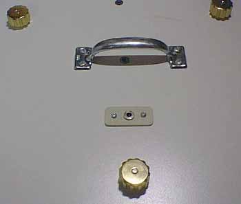
That’s it, your finished with the exception of testing the fans with a 12 volt power supply.
ADDITIONAL RECOMMENDED HARDWARE
To power your new cooling fans, I recommend the following DC cords.
1. Radio Shack Lighter Socket, DC Extension Cord with On/Off Switch, 10 foot. Part #270-1557 - This cord has a lighter socket at the other end so you can daisy chain an additional cord, below, in case you need the footage when connecting the cords to your cigarette lighter socket in your vehicle.2. Radio Shack Lighter Socket, Fuse - Protected Heavy Duty DC Power Cord, 8 foot. Part #270-1534E - This cord has the required male adapter at the other end that fits the Coaxial DC Power Jack you just installed onto the rear mirror mounting plate. This cord would be the only cord you will need if you are using a “Portable 12 volt Power Pac.” However, I do recommend both cords just in case you forgot to charge your power pac and need to run from your vehicles cigarette lighter socket. Eighteen (18) feet of power cords can come in pretty handy at times.
Please use "Back" button to return to previous page.